36+ regulated power supply block diagram
A power inverter inverter or invertor is a power electronic device or circuitry that changes direct current DC to alternating current AC. It has 54 digital inputoutput pins of which 12 can be used as PWM outputs 12 analog inputs 4 UARTs hardware serial ports a 84 MHz clock an USB OTG capable connection 2 DAC digital to.

Titan Solar Generator 4 000wh 5 X 100 Watt Solar Panels Flexible Solar Kit Free Shipping No Sales Tax Shopsolarkits Com
10 4 Ventilation 8 and safe load feeders 3RA71 A.

. It has 54 digital inputoutput pins of which 12 can be used as PWM outputs 12 analog inputs 4 UARTs hardware serial ports a 84 MHz clock an USB OTG capable connection 2 DAC digital to. 5922 The Shadow Five Switch and Diode PCB. When regulated voltage 311 volt is fed to H bridge always 220 volt AC is produced at the output of inverter.
Power BHP 186 226 266 306 Power kW 800 900 1000 1100 1200 1400 1600 1800 2000 2200 Engine Speed RPM Torque lb-ft 1085 1235 1385 1535 Torque N-m 1. The supply must use a coaxial center-positive 21mm or 25mm internal-diameter plug and provide a voltage of 7 to 15 Volts DC. Power control for high power solenoids.
From the block diagram the basic power supply is constituted by four elements viz a. Give your feedback by mailing me. Like other power supplies an SMPS transfers power from a DC or AC source often mains power see AC adapter to DC loads.
Regulated power supply is an electronic circuit that is designed to provide a constant dc voltage of predetermined value across load terminals irrespective of ac mains fluctuations or load variations. The resulting AC frequency obtained depends on the particular device employed. Part 2 master northern university bangladesh.
Inverters do the opposite of rectifiers which were originally large electromechanical devices converting AC to DC. D-11581-2016 with a special power supply board A-13502 NA. Sine wave inverter circuit diagram using microcontroller Arduino and program code SPWM using pic16f877a microcontroller.
The bridge rectifier diagram is also incorrectly rotated by 90 degrees. Curves shown above represent mature gross engine performance capabilities obtained and corrected in accordance with SAE J1349. The Arduino Due is a microcontroller board based on the Atmel SAM3X8E ARM Cortex-M3 CPUIt is the first Arduino board based on a 32-bit ARM core microcontroller.
The part of equipment that converts ac into dc is called DC power supply. The input voltage output voltage and. The Arduino Due is a microcontroller board based on the Atmel SAM3X8E ARM Cortex-M3 CPUIt is the first Arduino board based on a 32-bit ARM core microcontroller.
REGULATED POWER SUPPLY. A switched-mode power supply switching-mode power supply switch-mode power supply switched power supply SMPS or switcher is an electronic power supply that incorporates a switching regulator to convert electrical power efficiently. It is followed by a rectifier a diode circuita smoothing filter and then by a voltage regulator circuit.
1952 Chevrolet 31003604 relay diagram. An external power supply can be used by plugging into Power Jack J13. Make your own Electric Bug Zapper 22.
Fripple 50 Hz supply frequency Average output voltage is given as ie Area under one cycle. 6 list of figures page no. 63VAC supply for GI circuits.
Circuit diagram help from this book. Ideally the supply should be capable of providing 36 Watts of power 12 Volts DC 3 amps. Single Phase Half Wave Controlled Rectifier with RL load.
Block diagram of project 8 3. Ground for the relay is thru the mount to the firewall and ground to the horn is thru its mount or a separate ground wire. It works o ff a 12V DC power supply and consumes.
In general at the input of the power supply there is a power transformer. The supply should provide a minimum current of 1 amp. In addition which type of simulation.
When pressed it completes the circuit to ground pulls the plunger down on the relay and makes contact with the H terminal which supplies power to the horns. The fabrication of regulated dc power supply saurav dayal sing. I am using switch mode power supply topology in my project.
Power transferred to load Thus power voltage can be controlled by firing angle. Medical applications 34 9. Therefore T2πVoωt Vmsinωt from α to π for rest of the period Voωt0.
Block diagram of the project 8 a typical transformer 12 block diagram of voltage regulator 14. Regulated Power Supply Block Diagram.

12v Dc Power Supply Circuit Diagram Circuit Diagram Power Supply Circuit Electronics Circuit

Simple 12v Fixed Voltage Power Supply Circuit Diagram Diagram Circuit Power Supply Circuit Circuit Diagram Power Supply
2
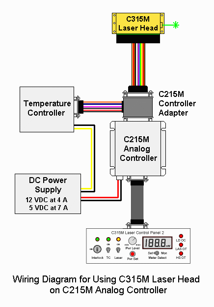
Sam S Laser Faq Commercial Solid State Lasers

Pin On Power Supply Circuit

Sam S Laser Faq Commercial Solid State Lasers

1 2 36v 5a Adjustable Power Supply With Lm317 Power Supply Circuit Electronic Schematics Electronic Engineering

Here This Circuit Diagram Is For 12v Regulated Fixed Voltage Dc Power Supply These Power Supply Circuit Power Supply Circuit Circuit Diagram Power Supply
2

Adding A New Separation Dimension To Ms And Lc Ms What Is The Utility Of Ion Mobility Spectrometry D Atri 2018 Journal Of Separation Science Wiley Online Library
How Do We Know Ketones And Not Glucose Is Our Brain S Preferred Fuel Source Since It Is A Relatively New Phenomenon Quora
2
Sam S Laser Faq Commercial Solid State Lasers

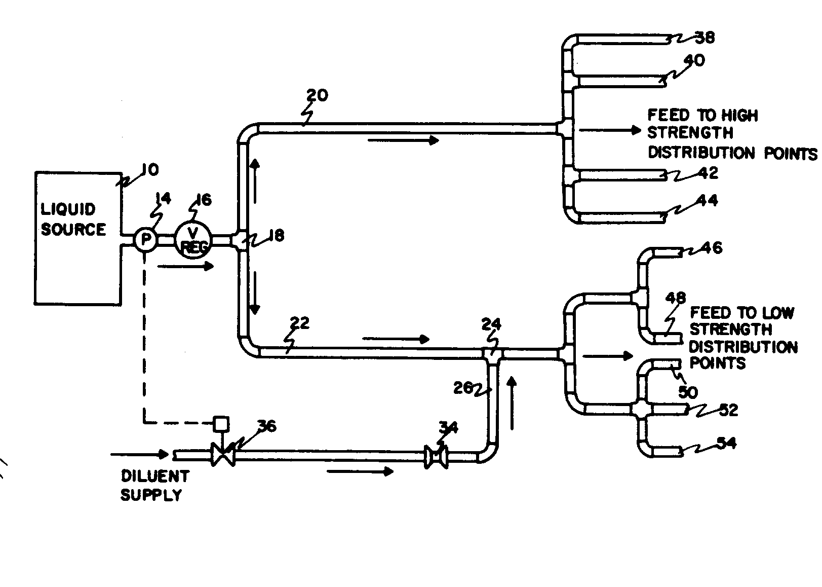
Class Definition For Class 137 Fluid Handling
2

Circuit Schematic Regulated Dc Power Supply Using Transistors Power Supply Design Power Supply Transistors
2